This year, I embarked on the endeavor of designing printed circuit boards (PCBs) to streamline firing multiple products on one cue utilizing a straightforward two-wire in and quick plug-out configuration. Traditionally, I would splice the initiators in series, a laborious and time-consuming process. Dissatisfied with the alternatives available on the market due to their pricing, I opted to take matters into my own hands. There’s nothing wrong with other PCBs in the market but I was able to make mine for about 20% of the cost and being I am going to use about 80 of these PCBs this year it is significant cost savings that can go towards product.
The journey involved various steps, from PCB design and parts procurement to locating a manufacturer and acquiring soldering skills. Because I kept encountering connector stock shortages with the Chinese manufacturer, I decided to undertake the soldering myself. I was able to get 20 of the 4SX1 PCBs assembled/soldered by the manufacturer, but the rest I am on my own. I placed an order for all of the connectors and jumpers from DigiKey and will be soldering onto the boards once they arrive next week.
All designs are “in-series”, necessitating jumpers for unused pins to complete the circuit. Being a novice in this domain, I recognize the importance of testing to ensure that the PCBs can handle the required current based on trace width and other factors. Preliminary calculations suggest my design will work, but empirical testing will provide definitive answers. More to come once I am able to test fully.
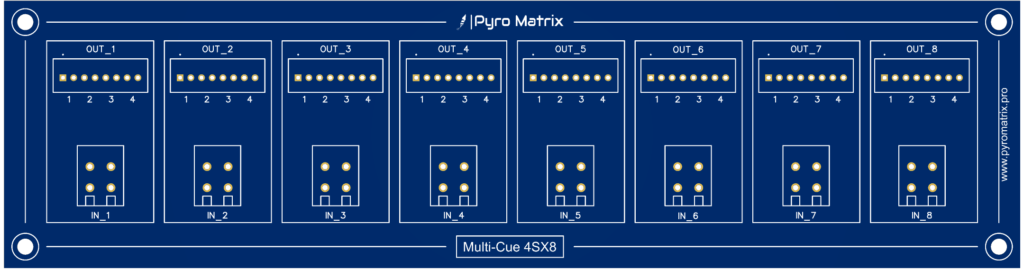
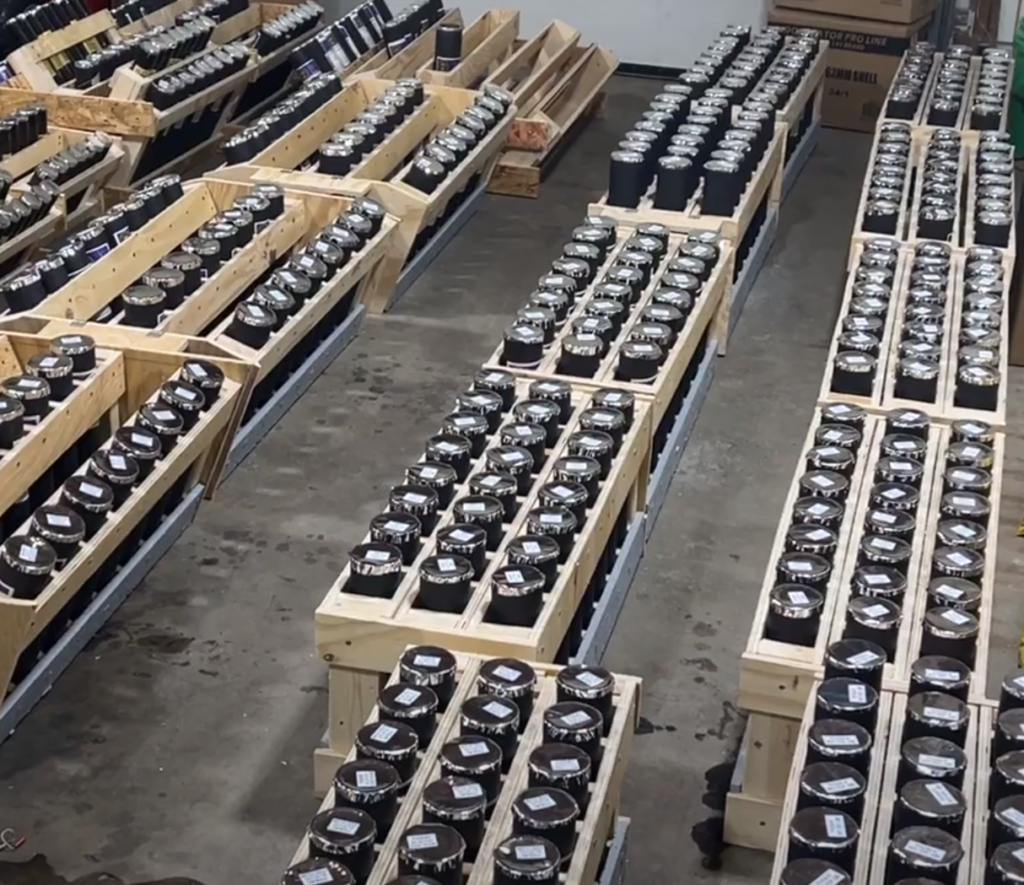
The initial design caters to mortar racks, featuring eight inputs and eight sets of four outputs. I often shoot 3 mortar shells at a time and will have an option for a fourth item to shoot with the 3 shells. Mounting this PCB on the mortar racks will facilitate the use of shorter and more economical MJG initiators. Although eight scab wires will still be necessary to connect to a slat or firing system, overall, this approach promises significant time and cost savings by eliminating the splicing of wires and reducing the length of MJG initiators required. This year I will shoot between 400 and 500 shells in a show, so initiator costs can add up quickly.
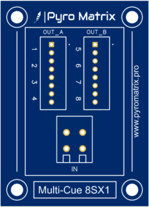
The second design is a 1 in and 8 out configuration. Useful for shooting up to 8 items at once. Think, comets, cakes, mines, etc.
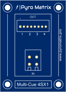
The third design is much like the second but only 4 outputs.
Once I get all of the PCBs shipped to me, I will do some testing and post videos and pics on this to show how I intend to utilize these.
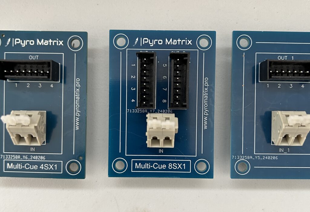
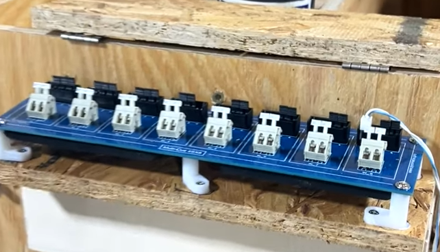
Here was one of my earlier prototypes that gives a better visual of what the board will look like once the connectors are soldered on.
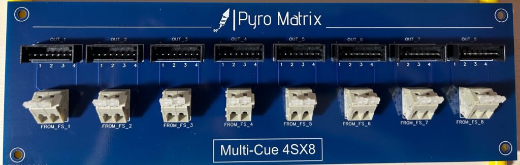
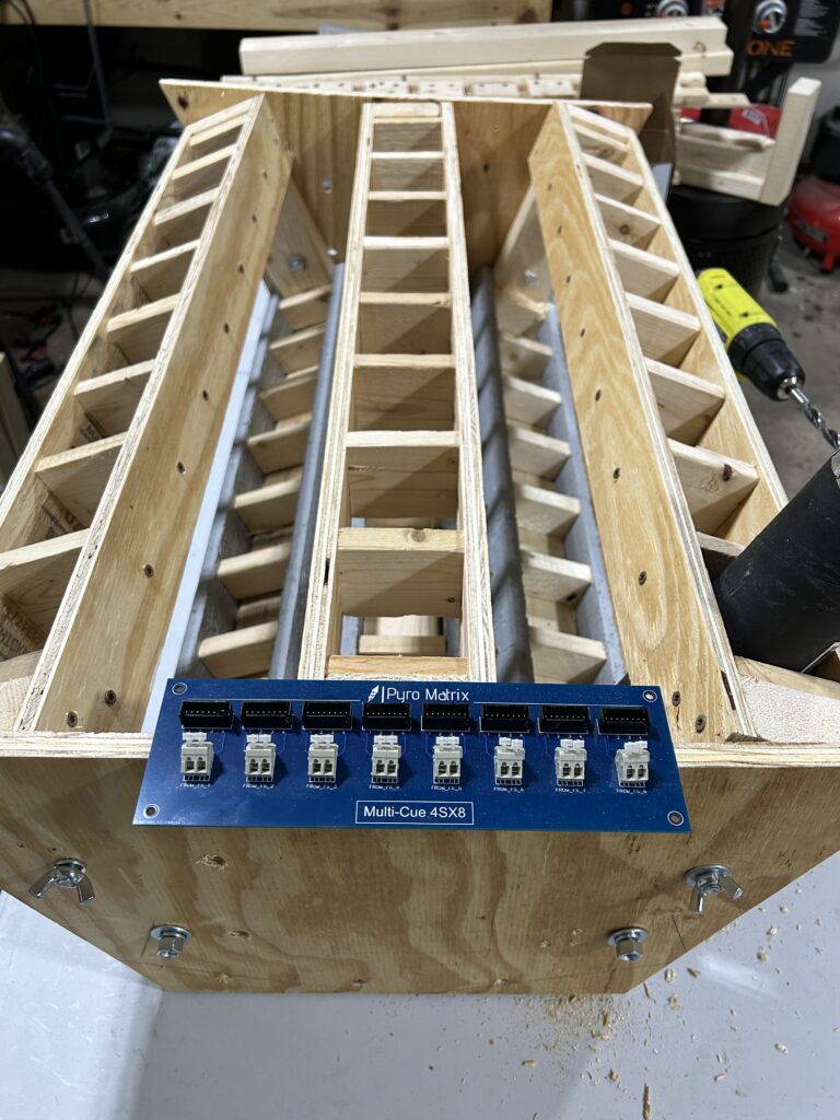
The size of the 4SX8 PCB is relatively large at 9.5″ x 2.5″. This was intentional and designed to be attached to the mortar rack. Still working on how and where I will attach. Want to make sure it is protected during the shows so still coming up with a feasible plan for this that doesn’t require over-priced 3D printed covers and backs. In the below picture you can see the size relative to my prototype rack.
Related Posts
Single Shot Racks
62 mm Mortar Rack with PCB Prototype